

Hydraulic fracturing process animation explains how a prepared oil or gas well is stimulated by isolating sections of the wellbore, perforating the production casing, pumping fluid and proppant at controlled pressure, and then allowing flowback and hydrocarbons to return through the well. A technically sound animation should make one distinction immediately: drilling creates the well, while hydraulic fracturing is a later completion operation used to create conductive pathways in low-permeability rock.
The process is difficult to communicate with surface footage alone. Pumps, blenders, manifolds, data vans, tanks, and the wellhead are visible above ground, but the decisive events occur thousands of feet below the surface. Animation can synchronize those two environments and show how pressure, fluid, perforations, fractures, proppant, and produced fluids relate over time.
This guide explains the sequence a scientifically credible hydraulic fracturing animation should show, the source data needed for accuracy, and the ways one visual model can support workforce training, stakeholder communication, technical sales, and public education.
Contact us at info@austinvisuals.com or call (512) 591-8024.
What Is Hydraulic Fracturing?
Hydraulic fracturing is a well-stimulation technique. A base fluid, proppant, and selected additives are pumped through a completed well at sufficient pressure to initiate and extend fractures in a target rock formation. Proppant, commonly sand or a manufactured granular material, remains in the fracture after pumping pressure declines. The propped pathway gives oil, natural gas, and formation fluids a more conductive route toward the wellbore.
The technique is often paired with horizontal drilling because a lateral wellbore can contact a longer interval of a low-permeability formation. The U.S. Energy Information Administration explains that horizontal wells expose more oil- or gas-bearing rock, while fracturing increases the permeability needed for fluid to move toward the well. These are complementary operations, not interchangeable names for the same event.
Hydraulic fracturing is also one part of a longer well lifecycle. Site preparation, drilling, casing, cementing, logging, completion, stimulation, flowback, production, maintenance, water management, and eventual closure may involve different crews and controls. A useful fracking process animation establishes this context before zooming into the treatment itself.
What Are the Main Stages of the Hydraulic Fracturing Process?
Completion designs differ by basin, geology, service company, well architecture, and operator. The sequence below is a conceptual model for a multi-stage treatment in a cased horizontal well. It should be adapted to the approved engineering program rather than presented as a universal equipment recipe.
1. Confirm Well Readiness and Pressure Integrity
Before stimulation, the relevant casing and cement system must be installed, and the well must be prepared for the pressures and temperature changes expected during the treatment. The animation should identify the wellhead, production casing or liner, cement sheath, target interval, and nearby protected formations without suggesting that every well uses an identical number of casing strings.
A pressure test, integrity check, or other readiness gate can be shown as an approved condition rather than a decorative gauge. If the training objective includes decision-making, the scene should connect the measured value to an acceptance limit and the action taken when the result is outside that limit.
2. Isolate and Access a Treatment Stage
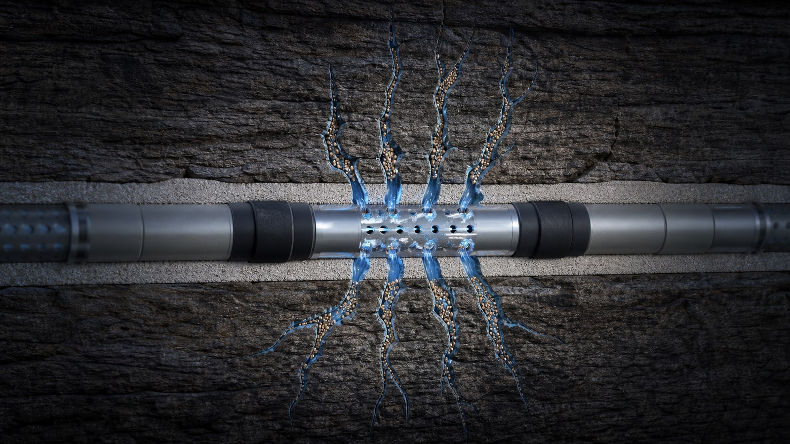
Long laterals are commonly treated in multiple stages. A stage is isolated from other portions of the wellbore using the completion system selected for that well. Perforating creates openings through the casing and cement into the target interval so treatment fluid can enter the formation. The animation must depict the actual completion method supplied by the client; plug-and-perf and sleeve-based systems should not be blended into an invented hybrid.
The camera can move from a full-well overview to a close cutaway of one treatment interval. This preserves spatial orientation while revealing the perforation cluster, casing wall, cement, and adjacent rock at a scale that field photography cannot provide.
3. Pump the Pad Fluid
The initial pad volume contains fluid without the main proppant concentration. Its purpose in the visual narrative is to establish the pressure pathway and initiate or extend the fracture system. Rather than showing the rock exploding, the animation should depict controlled fracture opening within a modeled treatment region. Fracture geometry is influenced by stress, geology, fluid behavior, pumping schedule, and nearby features; it is not a perfectly symmetrical set of glass-like cracks.
4. Introduce the Proppant Slurry
Proppant is blended into the treatment fluid and transported through the surface iron, wellhead, casing, perforations, and fractures. The visualization can use restrained color coding to distinguish base fluid, slurry, proppant, hydrocarbon, and returned water. Particle scale may need deliberate exaggeration for visibility, but the narration or legend should make that choice explicit.
The most important idea is transport and placement. Proppant does not create a hollow underground tunnel. It occupies part of a narrow fracture and helps preserve conductivity when pumping pressure is removed and the rock tends to close.
5. Flush, Stop Pumping, and Prepare the Next Stage
At the end of a treatment stage, the remaining slurry is displaced according to the program. Pumping is reduced or stopped, pressure behavior is observed, and the operation transitions to the next interval. In a multi-stage completion, the isolate-access-pump sequence is repeated along the lateral.
Animation can compress hours of repetitive activity into a short progression while preserving the logic. A stage counter, lateral map, or moving highlight can show where the active interval is located. Avoid making all stages appear simultaneous unless the specific system truly operates that way.
6. Manage Flowback and Begin Production
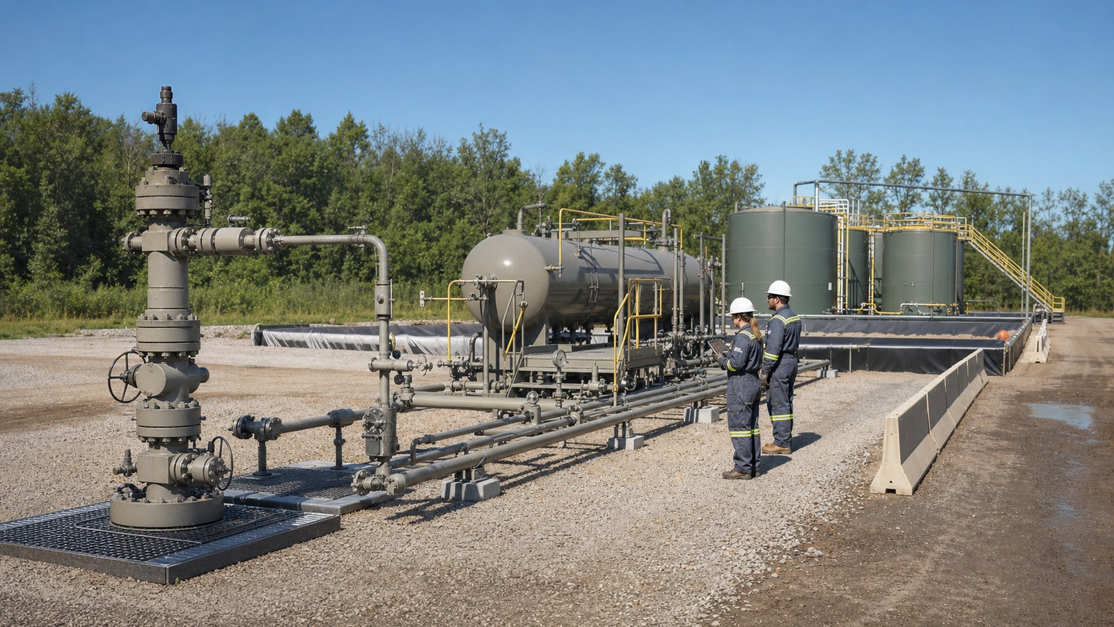
After stimulation, pressure is managed so fluid can return through the well. Flowback may contain injected fluid and naturally occurring formation constituents. Over time, the returning stream and hydrocarbon production are handled through the approved surface system. The EPA describes produced-water handling and wastewater disposal or reuse as distinct parts of the broader hydraulic fracturing water cycle.
The final underground scene should reverse the communication direction: oil or gas moves from the formation through the propped fracture network, enters the wellbore, and travels to the surface. This is the operational purpose of the treatment and gives the sequence a clear ending.
Why Is Animation Better Than Surface Footage for This Process?
A camera at the well pad records real equipment and activity, but it cannot see through casing, cement, or rock. A diagram can label those elements, but it usually freezes the process at one moment. A 3D oil and gas animation combines the strengths of both approaches: recognizable field context, accurate equipment relationships, controlled cutaways, and time-based cause and effect. A focused well stimulation animation can then isolate the pressure and material pathway without implying that the entire well lifecycle happens during the treatment.
The visual can hold the well geometry steady while switching layers on and off. One pass may show only casing and cement. The next adds perforations and pressure. Another follows proppant. A final pass changes the flow direction to production. Because the viewer does not have to rebuild the spatial model after every edit, more attention remains available for the actual lesson.
Animation also supports scale changes. The story can begin at a multi-well pad, descend through protected groundwater zones, follow the curved wellbore into the lateral, and finish at the fracture scale. Each transition should include an orienting cue so the audience understands where the camera moved and which dimensions have been exaggerated.
What Must Be Visible Above and Below Ground?
The Surface Frac Spread
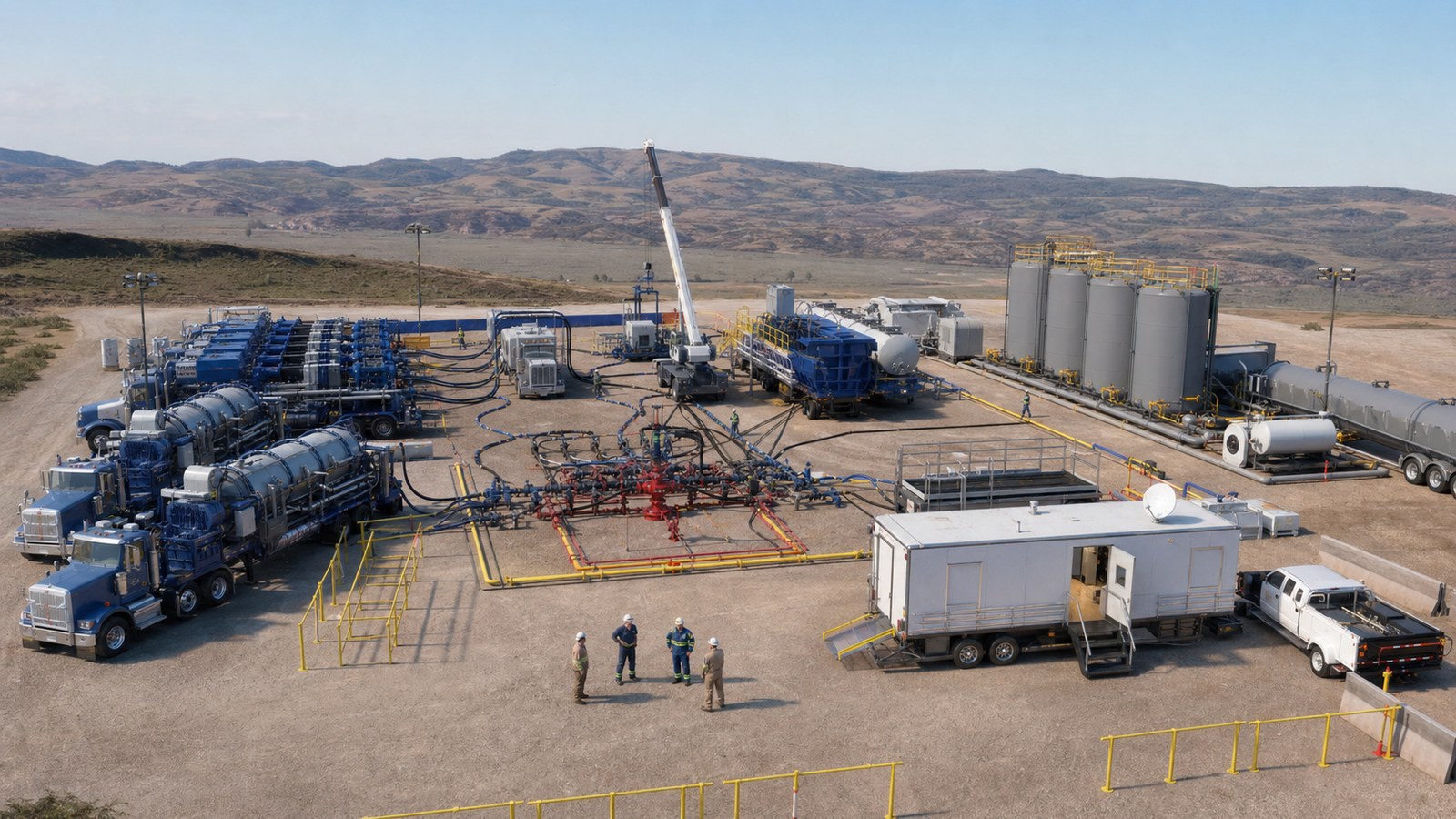
Depending on the project, the surface scene may include water storage, proppant handling, chemical systems, blenders, high-pressure pumps, manifolds, treating iron, monitoring equipment, a data van, the wellhead, flowback equipment, barriers, and vehicle routes. The objective is not to pack every asset into one beauty shot. It is to show the equipment chain relevant to the audience’s task.
For operator training, flow direction and line-up status may matter more than branded truck detail. For community communication, the relationship among the pad, water sources, roads, nearby land uses, and management facilities may be more important. For a technical sales presentation, a supplier’s component can be isolated inside the larger system without implying that it controls the whole operation.
The Well Architecture
A clean cutaway should identify only the casing, liner, cement, tubing, plugs, sleeves, perforations, or completion hardware relevant to the approved design. Showing every possible component creates false complexity. Omitting a critical barrier creates a misleading model. Technical reviewers should approve both the full-well arrangement and the detailed stage close-up.
The Formation Response
Subsurface imagery should communicate conceptual fracture propagation without claiming a degree of certainty the available data does not support. Geologic layers, stress orientation, natural features, treatment stages, and modeled fracture extent can be presented as separate layers. If geometry comes from simulation or interpretation, label it accordingly rather than presenting it as a direct underground photograph.
Time, Pressure, Rate, and Material State
Pressure and rate curves become more useful when synchronized with the scene that produced them. The viewer can see pumps ramp up as pressure increases, observe the active stage, follow proppant concentration, and then watch the transition after shut-down. Use real or clearly representative data and preserve units, time bases, and axis meaning.
How Do You Show Proppant and Fractures Accurately?
The fracture is a narrow, three-dimensional feature inside stressed rock, not an open cavern. In a teaching close-up, its width and the proppant grains may be enlarged so they remain visible. The animation should disclose this visual exaggeration through narration, a caption, or a scale cue.
Fluid should move from the wellbore through the perforations and into the fracture during pumping. Proppant travels with the slurry and settles or distributes according to the chosen conceptual model. After pressure falls, the fracture narrows around the proppant pack. During production, the dominant flow direction changes: reservoir fluids move through connected pathways toward the well.
Avoid uniform beads arranged in perfect rows unless the scene is explicitly symbolic. Natural variation in particle placement, fracture aperture, and formation texture makes the image more credible while still preserving legibility.

How Should Safety and Environmental Context Be Presented?
Safety animation should teach observable actions, interfaces, and decision points. Depending on scope, that may include pressure boundaries, red zones, line-of-fire awareness, high-pressure iron, hose and connection checks, silica exposure controls, chemical handling, traffic movement, hearing protection, emergency shutdown, and communication between the data van and field crews. OSHA places hydraulic fracturing within the well-completion phase and identifies flowback and worker exposure controls as related topics.
Environmental context should follow the complete material pathway. EPA’s five water-cycle stages are water acquisition, chemical mixing, well injection, produced-water handling, and wastewater disposal or reuse. A balanced visual can show these stages without implying that all water comes from one source or follows one management route.
Earthquake communication needs particular care. USGS states that most induced earthquakes in the central United States are associated with wastewater disposal rather than the hydraulic fracturing treatment itself. An educational scene should therefore distinguish short-duration stage pumping from longer-duration disposal operations and avoid assigning every seismic event to one cause.
Which Audiences Need Different Versions?
Field and Contractor Training
Training content should focus on roles, sequence, hazards, communication, and stop-work decisions. A hydraulic fracturing training video can pause at readiness gates, ask the learner to identify an abnormal condition, and then reveal the correct response. The visuals should match the operator’s equipment and procedures closely enough to support transfer to the field.
Engineering and Technical Sales
Engineers may need cutaways, component interfaces, stage logic, data overlays, assumptions, and failure boundaries. Sales audiences need enough technical evidence to trust the product without being buried in operating detail. A modular master model allows both versions to use the same approved geometry while changing narration and scene depth.
Executives, Investors, and Regulators
These viewers often need the relationship among capital equipment, schedule, operational control, production objective, water movement, and risk management. The animation should state what is representative, what is site-specific, and what has been simplified.
Community and Public Education
Public-facing content should define technical terms, maintain scale orientation, show protected resources and management pathways, and separate established facts from modeled behavior. Neutral language and visible source attribution improve credibility.
What Information Is Needed to Produce the Animation?
A technically reliable production begins with a source hierarchy. The client should identify which files control geometry, process logic, terminology, safety requirements, and visual branding. Useful materials may include:
- approved well schematics, casing and cement programs, and completion diagrams;
- equipment drawings, CAD files, photographs, and layout plans;
- stage sequence, perforation strategy, pumping schedule, and representative treatment data;
- fluid and proppant descriptions suitable for the intended audience;
- flowback, separation, storage, transfer, reuse, treatment, or disposal pathways;
- operating procedures, hazard analyses, exclusion-zone rules, and emergency actions;
- the audience, learning objective, distribution channel, runtime, and delivery formats; and
- named engineering, operations, HSE, legal, and communications reviewers.
Source conflicts should be resolved before detailed animation begins. A field photograph may show a later equipment revision than the CAD model. A generic schematic may use terminology that differs from the operator’s procedure. Recording these decisions in a visual source register protects accuracy and keeps review comments traceable.
What Is the Production Workflow?
Define the Learning or Communication Decision
Start with what the viewer should understand or do differently. “Explain hydraulic fracturing” is too broad. “Show how one isolated stage moves from perforation to proppant placement and production” is specific enough to storyboard and review.
Build the Technical Story Map
Lay out the sequence, active equipment, flow direction, pressure state, underground event, safety control, and required data for every scene. This map prevents the surface and subsurface stories from drifting apart.
Create Geometry and Visual Rules
Model the well, relevant equipment, and geologic context at the detail level required by the final camera distance. Approve color coding, transparency, scale exaggeration, flow particles, labels, and data styles before applying them across the project.
Review an Animatic Before Final Rendering
A low-detail animatic tests timing, camera orientation, sequence, and narration while revisions remain economical. Technical reviewers should approve causality and terminology at this stage. Final materials, lighting, effects, and high-resolution rendering follow after the process logic is stable.
Deliver a Reusable Visual System
Plan versions for widescreen presentations, learning platforms, mobile clips, event displays, and still images. Organizing the project by stage and information layer makes future revisions easier when equipment, procedures, or messaging change.
Why Choose Austin Visuals for Hydraulic Fracturing Animation?

Austin Visuals combines technical storytelling, 3D production, motion graphics, narration, and review management in one coordinated workflow. Our role is to turn engineering sources and operating knowledge into a visual sequence that a defined audience can follow without replacing the client’s technical authority.
For subsurface projects, we build the explanation from the inside out: geometry, barriers, active stage, material movement, pressure state, and operational outcome. Review checkpoints give engineering, operations, HSE, training, legal, and communications teams specific decisions to approve rather than asking everyone to comment on a nearly finished video at once.
Organizations planning a larger program can explore our oil and gas 3D animation services. Related examples include oil and gas drilling animation training and well control training animation. Each subject requires its own operational logic, even when approved equipment models are reused.
Our Clients include:

Conclusion
An effective hydraulic fracturing process animation does more than send colored fluid through a generic underground pipe. It distinguishes drilling from completion, establishes well integrity, locates the active stage, shows how pressure reaches the formation, explains proppant placement, reverses the flow for production, and follows returned water through a managed surface pathway.
The strongest result is built from approved sources and reviewed in layers. When surface equipment, well architecture, formation behavior, data, safety controls, and water management remain synchronized, one animation can support technical understanding without sacrificing clarity.
Contact us at info@austinvisuals.com or call (512) 591-8024.
Frequently Asked Questions
What is a hydraulic fracturing process animation?
It is a time-based visual explanation of well preparation, stage isolation, perforation, high-pressure fluid injection, fracture creation, proppant placement, flowback, and hydrocarbon production. It can synchronize surface equipment with events inside the well and formation.
Is hydraulic fracturing the same as horizontal drilling?
No. Drilling creates the wellbore, which may include a horizontal lateral. Hydraulic fracturing is a later well-stimulation operation that creates or extends conductive pathways in the target formation.
What does proppant do during hydraulic fracturing?
Proppant is carried into the fracture by the treatment fluid. After pumping pressure declines, the granular material helps keep part of the fracture conductive so oil, gas, and formation fluids can move toward the well.
Why are horizontal wells fractured in multiple stages?
Dividing a long lateral into treatment stages allows selected intervals to be isolated and stimulated in sequence. The number and design of stages depend on the well, completion system, geology, and treatment program.
What is the difference between flowback and produced water?
Flowback generally describes fluid returning soon after the treatment begins to flow back. Produced water is water brought to the surface during oil and gas production. Definitions and management categories can vary by operator and jurisdiction.
Can hydraulic fracturing animation be used for safety training?
Yes. It can show pressure boundaries, exclusion zones, line-of-fire hazards, equipment line-up, chemical and silica controls, flowback operations, communication steps, abnormal conditions, and emergency actions using the client’s approved procedures.
What source files are needed for an accurate animation?
Useful sources include well schematics, completion diagrams, equipment drawings or CAD, site layouts, stage sequences, representative pressure and rate data, operating procedures, hazard analyses, water-management plans, terminology standards, and named technical reviewers.